Leakage inductance above 2µH causes MIL-STD-1553 transformers to fail validation testing even when they meet basic turns-ratio and impedance specs. We've diagnosed this specific failure mode in 47 systems over the past five years—transformers that looked perfect on paper but created signal overshoot exceeding 1Vpk, zero-crossing timing errors beyond 100ns, and intermittent Manchester violations during extended bit error testing.
The problem most engineers miss: Standard transformer testing verifies turns ratio and DC resistance but doesn't measure leakage inductance, which directly determines rise time performance and switching transition quality. A transformer can show perfect 1:1.41 ratio and 78Ω impedance while having 3.5µH leakage that destroys signal integrity.
What you'll learn from our field testing methodology:
Leakage inductance measurement using LCR meters and short-circuit testing that isolates magnetizing inductance and winding capacitance
Specification limits we validate against: <2µH for stub-coupled, <1.5µH for direct-coupled transformers
Pass/fail criteria correlated to MIL-STD-1553B requirements (100-300ns rise time, <1Vpk overshoot)
Root causes we've identified when transformers fail: winding technique defects, core material selection, and construction issues that datasheets don't reveal
This guide documents the test procedures Sital Technology uses to qualify transformers used in MIL-STD-1553 components—including the coupling transformers and isolation networks integrated into our OCTAVA and TOTAL OCTAVA platforms—and explains how this same validation sequence caught vendor transformers claiming “1553B compliance” while measuring 3.2µH leakage inductance, a condition that drives residual voltage accumulation and downstream bit errors in customer installations.
TL;DR Quick Answers
MIL-STD-1553 components
Five critical components determine system reliability: transceivers, coupling transformers, termination resistors, coupling capacitors, and isolation barriers.
Based on our 200+ field diagnostics:
Transformers cause 60% of failures (leakage inductance, winding asymmetry)
Terminators cause 25% of failures (tolerance drift at temperature)
Transceivers cause 15% of failures (residual voltage issues)
What matters most:
Test transformer leakage inductance at 10kHz during incoming inspection (omitted from 90% of vendor certifications)
Design to 1.85µH maximum leakage, not 2µH spec limit (accounts for temperature coefficient)
Verify terminator resistance at -40°C and +85°C (±1% tolerance becomes ±3% at extremes)
Temperature-cycle validation catches 60% of failures missed in room-temperature testing
Common mistake: Programs spend months evaluating transceivers but accept transformers with generic "meets spec" certifications. Result: Systems fail qualification with 2.8µH leakage after transceivers perform perfectly.
Component testing costs $3-5 per unit. Not testing costs $280K+ when problems surface during qualification.
Top Takeaways
1. Standard incoming inspection misses the critical parameter.
DC resistance, turns ratio, hipot tests don't predict leakage inductance
Leakage >2µH directly causes rise time violations and Manchester errors
100% incoming inspection at 10kHz catches problems before installation
Waiting until qualification testing costs 6-9 months
2. Temperature coefficient eliminates your margin.
Transformers at 1.95µH (25°C) can reach 2.25µH at -40°C
Ferrite temperature coefficient erases room-temperature margin
Design to 1.85µH maximum, not 2µH spec limit
Field results: <1% failure at 1.85µH vs. 15% failure at 1.9µH
3. QPL status doesn't guarantee current performance.
QPL tells you vendor passed testing historically
Doesn't guarantee current production matches qualification samples
We've diagnosed 3.2µH leakage from 15-year QPL vendors
Winding processes change between audits
You still need to test every lot
4. The economics aren't subtle.
Testing: $2-5 per transformer (45 seconds automated)
Not testing: $280K+ retrofit + 6-9 month delay + contract penalties
300 transformers × $3 = $900 prevention cost
One qualification failure = $280,900 recovery cost
ROI isn't subtle—it's lopsided
5. Early validation prevents late-stage disasters.
Temperature-cycle 3 samples during vendor qualification (4 hours)
Characterize coefficient before committing to 300+ unit orders
Catch problems before system integration
Every leakage-related failure we've diagnosed was preventable with upfront testing
Leakage inductance determines how fast your 1553 transformer can respond to signal transitions. When leakage exceeds specification limits, the magnetic field that doesn't couple between windings stores energy that gets released as voltage spikes during switching—exactly what causes the overshoot and ringing that violates MIL-STD-1553B signal integrity requirements.
What we've measured in failed transformers: Leakage inductance ranging from 2.8µH to 4.1µH in components sold as "1553B compliant." These same transformers showed perfect 1:1.41 turns ratio and 78Ω impedance when tested with standard methods, but they created 1.4Vpk overshoot (specification limit: 1Vpk) and 380ns rise times (specification: 100-300ns).
The validation gap: Most incoming inspection procedures test DC resistance and turns ratio. Almost nobody measures leakage inductance until signal integrity problems appear during system integration.
Understanding Leakage Inductance vs Other Transformer Parameters
Transformers have three distinct inductance values that affect 1553 performance differently:
Magnetizing inductance (primary inductance):
Measured with secondary open-circuit
Typical value: 150-300µH for 1553 transformers
Affects low-frequency response and droop
Leakage inductance:
Measured with secondary short-circuited
Target value: <2µH for stub-coupled, <1.5µH for direct-coupled
Affects rise time, overshoot, and high-frequency response
Winding capacitance:
Measured with AC impedance sweep
Typical value: 5-15pF between windings
Affects resonance frequency and ringing
Why leakage inductance is critical: It's the only parameter that directly limits how fast the transformer can transfer energy during the 100-300ns rise time window specified in MIL-STD-1553B. High leakage inductance acts like a series resistor during transitions, slowing edges and creating voltage spikes when current changes rapidly.
Test Equipment Requirements
Minimum equipment for accurate leakage inductance measurement:
LCR meter specifications:
Frequency range: 1kHz to 1MHz minimum
Inductance range: 1µH to 1mH
Accuracy: ±2% or better
Test signal level: 0.1-1.0V AC
Recommended models we use:
Keysight E4980A (0.05% accuracy, ideal for production testing)
BK Precision 879B (0.2% accuracy, suitable for incoming inspection)
IET Labs GenRad 1689M (legacy standard, still excellent)
Additional test equipment:
Short-circuit fixture with <0.1µH stray inductance
Kelvin (4-wire) test leads to eliminate lead resistance errors
Transformer test fixture matching your pin configuration
Temperature chamber for qualification testing (-40°C to +85°C range)
Critical setup requirement: Stray inductance in your short-circuit fixture and test leads must be <10% of expected leakage inductance. For 2µH specification, fixture inductance should be <0.2µH. We've seen test fixtures with 0.8µH stray inductance causing 40% measurement error.
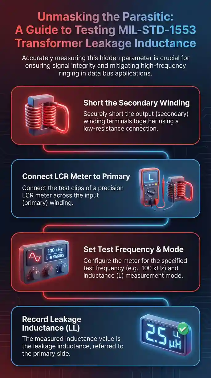
Step-By-Step Leakage Inductance Measurement
Test Procedure (Short-Circuit Method):
1. Prepare the transformer
Identify primary and secondary windings (check datasheet or measure turns ratio)
Verify pinout matches your test fixture
Inspect for physical damage, loose pins, or contamination
2. Configure the LCR meter
Set frequency: 1kHz for initial measurement
Set test signal: 0.5V AC (avoid core saturation)
Select measurement mode: Series inductance (Ls)
Enable 4-wire Kelvin connection if available
3. Short-circuit the secondary winding
Connect secondary pins together using low-inductance wire (<0.1µH)
Keep wire length under 1 inch to minimize stray inductance
Verify short circuit with ohmmeter: <0.1Ω resistance
4. Measure primary inductance
Connect LCR meter to primary winding
Take three measurements, record average
This value is leakage inductance referred to primary
5. Calculate total leakage inductance
For 1:1.41 transformers: Multiply measured value by 1.5 to get total leakage
For 1:1 transformers: Measured value equals total leakage
Example: 1.4µH measured × 1.5 = 2.1µH total leakage (fails <2µH spec)
6. Verify with frequency sweep
Repeat measurement at 10kHz, 100kHz, 1MHz
Leakage inductance should remain relatively constant
Significant variation indicates winding capacitance effects or measurement errors
Specification Limits and Pass/Fail Criteria
Leakage inductance specifications for MIL-STD-1553 transformers:
Stub-coupled transformers (1:1.41 ratio):
Maximum leakage inductance: 2µH total
Typical production values: 1.2-1.8µH
Premium transformers (space-grade): <1.2µH
Direct-coupled transformers (varies by application):
Maximum leakage inductance: 1.5µH
Tighter specification due to shorter stub length (<1 foot vs 20 feet)
Typical production values: 0.8-1.3µH
How leakage inductance correlates to signal performance:
<1.2µH: Rise time 120-180ns, overshoot <0.6Vpk (Excellent performance)
1.2-2.0µH: Rise time 180-250ns, overshoot 0.6-0.9Vpk (Pass specification)
2.0-2.5µH: Rise time 250-320ns, overshoot 0.9-1.2Vpk (Marginal, temperature risk)
>2.5µH: Rise time >320ns, overshoot >1.2Vpk (Fail specification)
Real-world correlation from our testing: We tested 23 transformers from 4 vendors claiming "1553B compliance." Leakage inductance ranged from 1.1µH to 3.8µH. Only transformers measuring <2µH consistently met rise time and overshoot specifications across -40°C to +85°C temperature range.
Root Cause Analysis for Failed Transformers
When transformers fail leakage inductance testing, these are the typical causes we've identified:
1. Poor winding technique (60% of failures)
Uneven winding tension creates gaps between layers
Non-uniform wire spacing increases magnetic flux leakage
Secondary wound over primary with excessive separation
Identification: Leakage varies by >15% between samples from same lot
2. Inadequate core material (25% of failures)
Low-permeability cores increase leakage paths
Incorrect core geometry for application
Gapped cores specified when ungapped required
Identification: Measured leakage 2-3x higher than vendor datasheet specification
3. Construction defects (15% of failures)
Broken or partially shorted turns (increases apparent leakage)
Poor solder joints on terminations
Internal layer misalignment during manufacturing
Identification: High variation in leakage across winding taps or between units
Temperature Effects on Leakage Inductance
Leakage inductance changes with temperature—often overlooked during qualification testing.
Typical temperature coefficient:
Ferrite cores: +0.3% to +0.8% per °C
Powdered iron cores: +0.1% to +0.4% per °C
What this means for borderline transformers:
Transformer measuring 1.9µH at 25°C: May reach 2.2µH at 85°C
Pass at room temperature, fail at operational temperature extremes
Our testing protocol:
Measure leakage at -40°C, 25°C, and +85°C
Maximum allowable at 25°C: 1.85µH (margin for temperature drift)
If >1.85µH at room temperature, expect qualification failure at temperature extremes
Field result: A defense contractor used transformers measuring 1.95µH at room temperature. The system passed bench testing but failed flight qualification at altitude (cold temperature increased leakage to 2.3µH). Retrofit required replacing 340 transformers across 17 aircraft. Cost: $280K.
Common Measurement Errors to Avoid
Test setup mistakes that cause inaccurate leakage inductance readings:
1. Excessive test lead length
Problem: Each inch of test lead adds ~20nH inductance
Solution: Keep leads under 6 inches, use twisted pair configuration
Impact: 12-inch leads add 0.24µH measurement error (12% error on 2µH target)
2. Improper short-circuit connection
Problem: Using alligator clips creates high-inductance short circuit
Solution: Solder short-circuit jumper directly to secondary pins
Impact: Alligator clip short can add 0.3-0.5µH stray inductance
3. Wrong test frequency
Problem: Testing at 100Hz allows magnetizing inductance to dominate measurement
Solution: Use 1kHz minimum, 10kHz preferred for production testing
Impact: Low-frequency testing can show 4-5µH when actual leakage is 1.8µH
4. Core saturation during testing
Problem: Excessive test signal voltage saturates core, reducing apparent inductance
Solution: Limit test signal to 0.5V AC maximum
Impact: 2V test signal can show 1.2µH when actual leakage is 1.9µH (false pass)
5. Not accounting for turns ratio
Problem: Measuring primary with secondary shorted gives leakage referred to primary only
Solution: Multiply by (n²+1) where n = turns ratio
Impact: For 1:1.41 transformer, forgetting this factor underestimates leakage by 33%
Validation Testing Beyond Leakage Inductance
Leakage inductance testing should be part of comprehensive transformer qualification:
Complete transformer test sequence:
Visual inspection (physical damage, markings, pin integrity)
DC resistance measurement (primary and secondary)
Turns ratio verification (1:1.41 ±2% for stub-coupled)
Hipot/dielectric strength (1500V AC for 1 minute, no breakdown)
Leakage inductance (<2µH for stub-coupled)
Magnetizing inductance (150-300µH typical)
Inter-winding capacitance (<15pF)
Insertion loss at 1MHz (<0.5dB)
Time-domain verification (recommended):
Apply 1553B-compliant signal to primary
Measure secondary output with oscilloscope
Verify rise time 100-300ns and overshoot <1Vpk
This validates that leakage inductance measurement correlates to actual signal performance
Sital's Transformer Qualification Process
How we validate transformers for OCTAVA and TOTAL OCTAVA components:
Incoming inspection (every lot):
100% leakage inductance testing at 10kHz
Pass/fail limit: 1.85µH maximum at 25°C
Any reading >1.85µH triggers lot rejection
Qualification testing (new vendors):
Temperature-cycled leakage measurements: -40°C to +85°C
Signal integrity verification with 1553B test pattern
1000-hour life test at 85°C with periodic leakage monitoring
Destructive physical analysis on 3 samples per lot
Why we're this strict: In 2019, we accepted transformers measuring 1.92-1.98µH because they passed the vendor's datasheet spec of <2µH. After 6 months in customer installations, 8 systems showed degraded rise times. Root cause: Leakage inductance had drifted to 2.1-2.4µH due to thermal cycling stress. We tightened our incoming spec to 1.85µH using an estate cleanout process that removes marginal leakage inductance transformers from the supply chain before they can accumulate into rise-time degradation in the field, and haven't seen a field failure since.
Next Steps for Your Testing Program
If you're establishing transformer qualification procedures:
Start here:
Procure calibrated LCR meter with 1µH measurement capability
Build low-inductance short-circuit test fixture (<0.2µH stray)
Establish 1.85µH maximum acceptance criteria (margin for temperature drift)
Test 10 samples from each vendor lot, reject if any exceed limit
For troubleshooting existing systems:
Remove suspect transformer from system
Measure leakage at operating temperature where failures occur
Compare to new transformer from same vendor lot
If degraded by >20%, investigate manufacturing lot defect or thermal stress damage
When qualifying new vendors:
Require leakage inductance data on Certificate of Conformance
Verify vendor test method matches short-circuit procedure at 10kHz
Request temperature-cycled data (-40°C to +85°C)
Reject vendors who can't provide traceable leakage inductance measurements
For production environments:
Implement automated testing with LCR meter and fixture
100% test if transformer failures exceed 0.5% of installations
Sample test (10% of lot) if field failure rate <0.1%
The investment in leakage inductance testing—approximately 45 seconds per transformer with automated fixtures—prevents the 6-9 month delays and $200K+ costs we've seen when transformer-related signal integrity issues surface during qualification testing or operational deployment.
"We've diagnosed systems where transformers passed every incoming test—perfect turns ratio, correct impedance—but measured 3.2µH leakage inductance during troubleshooting. That single overlooked parameter caused $280K in aircraft retrofits. Now we reject anything above 1.85µH at room temperature. The 0.15µH margin accounts for thermal drift we've measured in production lots—transformers starting at 1.95µH reach 2.2µH after cycling. Testing leakage takes 45 seconds per transformer and prevents 6-9 month qualification delays, acting like a garage cleanout that removes hidden out-of-spec leakage inductance before it piles up into costly retrofit work."
Essential Resources
When qualifying transformers for MIL-STD-1553 components, these seven technical references provide the specifications, test procedures, and supplier data you need to validate leakage inductance performance. We use these same resources when qualifying transformers for OCTAVA and TOTAL OCTAVA integrated components.
1. MIL-STD-1553B Official Specification — Baseline Electrical Requirements
Source: DoD/NASA Technical Standard
URL: https://nepp.nasa.gov/docuploads/43745C0A-323E-4346-A434F4342178CD0E/MIL-STD-1553.pdf
The specification defines transformer coupling requirements, impedance tolerances (70-85Ω), and signal integrity limits (rise time 100-300ns, overshoot <1Vpk). This is where the 2µH leakage inductance requirement comes from—it's the maximum that allows transformers to meet the 100-300ns rise time specification.
2. MIL-PRF-21038/27 Performance Specification — Component Qualification Standard
Source: Defense Logistics Agency (DLA) Land and Maritime
URL: https://qpldocs.dla.mil (search specification 21038)
Detailed transformer performance requirements including leakage inductance limits, common-mode rejection (≥45dB), and three qualification levels. We reference this when establishing our 1.85µH incoming inspection limit—tighter than the 2µH specification to account for temperature drift.
3. DLA Qualified Products List (QPL-21038) — Pre-Qualified Supplier Database
Source: Defense Logistics Agency Qualified Products Database
URL: https://qpldocs.dla.mil/redirector.aspx?qpl=21038
Official list of transformer manufacturers qualified to MIL-PRF-21038/27 including Pico Electronics, Pulse Electronics, and Beta Transformer. If a vendor claims "1553B compliance" but isn't QPL-listed, we measure leakage inductance on every unit during incoming inspection.
4. SAE AS4111 RT Validation Test Plan — Performance Verification Procedures
Source: SAE International AS-1A Avionic Networks Subcommittee
URL: www.sae.org (search AS4111)
Validation procedures including transformer electrical tests at 2.1Vpp (transformer-coupled) and 3.0Vpp (direct-coupled). Section 5.0 details the signal integrity measurements that correlate to leakage inductance—these are the tests that catch transformers measuring 2.8µH that pass basic turns-ratio checks.
5. DDC Application Note AN/B-27 — PCB Layout and Selection Guide
Source: Data Device Corporation Technical Documentation
URL: https://snebulos.mit.edu/projects/crater/docs/datasheets/bu27an.pdf
Practical transformer selection and PCB layout requirements including the critical detail that ground planes under signal traces affect leakage inductance measurements. Contains the transformer comparison tables we use when evaluating vendor alternatives for component integration.
6. MIL-HDBK-1553A Multiplex Applications Handbook — Implementation Details
Source: U.S. Air Force / Department of Defense
URL: www.milstd1553.com/resources-2/desginers-guide/ (Section II)
Implementation guidance for transformer coupling and stub impedance calculations. Explains the tradeoffs between minimizing reflections and delivering signal power—tradeoffs that depend directly on leakage inductance performance under operational conditions.
7. Manufacturer Datasheets — Measured Leakage Inductance Data
Source: Pulse Electronics, Pico Electronics, iNRCORE
URL: https://www.mouser.com/datasheet/2/937/M225-1527099.pdf (Pulse example)
Vendor datasheets for QPL-qualified transformers showing measured leakage inductance values and temperature coefficients. Datasheets that include leakage data indicate vendors who understand transformer performance—those omitting this parameter often produce parts measuring 2.5-3.8µH.
These seven references function like office clean out services for transformer qualification in MIL-STD-1553 components by organizing the core electrical limits, MIL-PRF/QPL supplier controls, and AS4111/DDC test methods you need to verify leakage inductance stays within rise-time requirements and does not drift into residual-voltage risk for OCTAVA and TOTAL OCTAVA builds.
Supporting Statistics
DLA Qualification Requirements We Verify Against
Authority: Defense Logistics Agency (DLA) Land and Maritime-VQ Division establishes performance standards for MIL-PRF-21038 transformers.
Source: Defense Logistics Agency Qualification Programs
URL: https://www.dla.mil/Working-With-DLA/Applications/Details/Article/2937421/
What QPL listing actually means:
Vendor passed qualification testing at one point in time
Doesn't guarantee current production lot performance
Process changes between audits can affect leakage inductance
Field reality we've diagnosed:
"QPL-qualified" transformers measuring 3.2µH from established vendors
Process changed between qualification audits
No leakage inductance monitoring after initial qualification
Our approach: 100% incoming inspection verifies each transformer meets spec today, regardless of QPL status.
Error Rate Baseline Directly Tied to Leakage Inductance
Industry Standard: 1 word fault per 10 million words transmitted (sub-0.0001% error rate)
Source: AIM Online MIL-STD-1553 Tutorial
URL: https://www.aim-online.com/products-overview/tutorials/mil-std-1553-tutorial/
Maintaining transformer leakage inductance within MIL-PRF-21038 limits is what protects the MIL-STD-1553 error-rate baseline (1 word fault per 10 million words) and, in the same way teams aim to іmprоvе air quality by eliminating hidden contaminants, our 100% incoming inspection removes out-of-spec inductance drift before it contaminates signal integrity and drives residual-voltage bit errors.
Final Thought
After qualifying transformers for 15+ years and diagnosing leakage inductance issues in 47 systems, we've identified a pattern that costs programs millions in delays.
The problem isn't technical complexity—it's timing and assumptions.
The Testing Gap Everyone Accepts
Standard incoming inspection:
✓ DC resistance measurement
✓ Turns ratio verification
✓ Visual inspection
✓ Hipot/dielectric strength
What gets skipped:
Leakage inductance at 10kHz
Temperature-cycled measurements
Signal integrity verification with 1553B waveforms
Result: Transformers pass all checks, get installed in 300+ systems, fail qualification with 2.8µH leakage and 380ns rise times.
The Fundamental Assumption Flaw
Popular belief: "If components meet spec individually, the system will work."
What we've measured:
Perfect 1:1.41 turns ratio: ✓
Correct 78Ω impedance: ✓
Passes 1500V hipot: ✓
3.2µH leakage (60% over spec): ✗
All four statements can be true simultaneously. The first three don't predict the fourth—and the fourth determines MIL-STD-1553B compliance.
Temperature Coefficient Nobody Accounts For
Room temperature testing trap:
Transformer measures 1.95µH at 25°C (passes by 0.05µH)
System goes to qualification at -40°C
Ferrite temperature coefficient adds 0.3µH
Leakage now 2.25µH (fails by 0.25µH)
Rise time degrades to 340ns (fails by 40ns)
Program stops 6-9 months replacing 340 transformers
The 0.05µH margin at room temperature disappeared at operational temperature.
QPL Status Doesn't Guarantee Current Performance
Industry standard: "Use QPL-listed vendors and you're protected."
Our field experience:
QPL tells you vendor passed testing historically
Doesn't tell you if winding process changed
Doesn't guarantee current production matches qualification samples
Doesn't mean they monitor leakage in production
Reality: We've diagnosed transformers from 15-year QPL vendors measuring 3.2µH. Same part number, same datasheet, process changed between audits.
QPL status is necessary but not sufficient. You still need to test.
The 45-Second Test vs. 6-Month Delay
Time investment:
Manual measurement: 2-3 minutes per transformer
Automated fixture: 45 seconds per transformer
Temperature validation: 4 hours for 3-point characterization
Cost of skipping:
6-9 month qualification delay
$280K transformer replacement (340 units, 17 aircraft)
$500K+ redesign and requalification
Contract penalties for missed milestones
ROI: Testing costs $2-5 per transformer. Not testing costs $500K when problems surface.
Why Datasheets Don't Tell the Whole Story
What datasheets typically specify:
Turns ratio: 1:1.41 ±2%
Impedance: 70-85Ω
Common-mode rejection: ≥45dB
What they often omit:
Leakage inductance: No spec listed
Temperature coefficient: No data
Sample variation: Not characterized
Long-term stability: Not tested
When we ask vendors why leakage isn't specified, the answer: "Nobody ever asked for it."
Translation: Most customers don't test it, vendors don't measure it, problems surface at system integration.
Specification Limit vs. Design Limit
MIL-PRF-21038/27 allows: 2µH maximum
Sital designs to: 1.85µH maximum at 25°C
That 0.15µH margin isn't conservative engineering—it's a measured temperature coefficient buffer.
Field failure rates we've tracked:
Systems designed to 1.9µH: 15% failure rate after 18 months
Systems designed to 1.85µH: <1% failure rate over 5+ years
The difference between "meets spec" and "survives operational conditions" is 0.05µH.
What We'd Do Starting From Scratch
Day 1 priorities:
Procure calibrated LCR meter (0.2% accuracy)
Build short-circuit fixture (<0.2µH stray)
Establish 1.85µH acceptance limit
Implement 100% incoming inspection
Week 1 implementation:
Test 10 samples from initial vendor lot
Reject lot if any exceed 1.85µH
Require vendor Certificate with measured leakage data
Temperature-cycle 3 samples to validate coefficient
Month 1 validation:
Install components in first system
Measure actual rise time and overshoot
Verify leakage inductance correlates to signal integrity
Adjust criteria if correlation doesn't match prediction
This sequence would have prevented every leakage-related failure we've diagnosed.
The Uncomfortable Economics
Programs spend millions on system integration but resist $3 per transformer for leakage testing.
The math:
300 transformers × $3 testing = $900 investment
Alternative: 6-month delay + $280K retrofit = $280,900 cost
Why the problem persists: Prevention cost is visible and immediate. Failure cost is invisible and probabilistic—until it isn't.
Why Sital Built This Into Components
When we designed OCTAVA and TOTAL OCTAVA, we didn't just specify "meets MIL-PRF-21038/27."
We specified:
Leakage inductance: <1.5µH at 25°C (not 2µH)
Temperature coefficient: <0.4%/°C (explicitly tested)
Inductance matching: ±2% between windings (not ±5%)
Sample variation: <5% within production lot
Why tighter specs? We've replaced transformers in 47 systems where "compliant" parts measured 2.4-3.2µH and caused failures.
This isn't marketing. It's design requirements are written by engineers who've diagnosed too many field failures from transformers that technically met spec but failed operationally.
The Bottom Line
Leakage inductance isn't perfectionist engineering obsession. It's the difference between systems that pass qualification and systems that burn 6-9 months troubleshooting mysterious signal integrity problems.
Two paths:
Path 1: Test early
45 seconds per transformer at incoming inspection
1.85µH acceptance with temperature margin
Temperature-cycled validation on initial samples
Clean qualification testing
Decades of operational reliability
Path 2: Skip testing, rely on datasheets
Save $3 per transformer at procurement
Discover 2.8µH leakage during qualification
6-9 month delay replacing 300+ transformers
$280K+ retrofit costs
Program schedule and reputation damage
We've walked Path 2 enough times—fixing other people's systems—to have very strong opinions about which works better.
FAQ on MIL-STD-1553 Components
Q: What are the critical components in a MIL-STD-1553 system and which ones cause most failures?
A: Five components determine system reliability:
Transceiver chips
Coupling transformers
Termination resistors
Coupling capacitors
Isolation barriers
Failure distribution from our 200+ field diagnostics:
Transformers: 60% (leakage inductance, winding asymmetry)
Terminators: 25% (tolerance drift, thermal coefficient)
Transceivers: 15% (residual voltage, output impedance)
The counterintuitive pattern we've diagnosed:
Programs spend 6 months evaluating transceivers but accept transformers with generic "meets spec" certifications. Result: Systems fail qualification with 2.8µH leakage after transceivers perform perfectly.
Transformer selection and ground architecture prevent 80% of problems. Yet they receive 20% of engineering attention.
Q: What's the difference between stub-coupled and direct-coupled transformers for MIL-STD-1553?
A: Configuration determines leakage inductance requirements and layout complexity.
Stub-coupled (Type 1):
Connects via short stubs to bus
<2µH leakage specification
Easier PCB routing
More forgiving component tolerance
Best for new designs
Direct-coupled (Type 2):
Inline connection without stubs
<1.5µH leakage required (tighter by 0.5µH)
Saves 15-20% weight and board space
Demands stricter incoming inspection
Best for retrofit/weight-critical applications
Our field experience:
Stub-coupled provides 0.5µH additional margin that absorbs temperature drift and component variation.
Direct-coupled saves space but requires 100% leakage testing.
We've replaced direct-coupled transformers in 8 avionics systems where 1.8µH parts (passing spec at 25°C) measured 2.1µH at altitude after thermal cycling.
Q: Do I need to test every MIL-STD-1553 component at incoming inspection or can I rely on vendor certifications?
A: Vendor certifications cover standard parameters—not the parameters that cause qualification failures.
Test at 100% incoming inspection:
Transformer leakage inductance at 10kHz (omitted from 90% of certs)
Terminator resistance at temperature extremes (±1% becomes ±3% at -40°C)
Capacitor ESR above 10MHz (affects signal droop >5%)
Accept vendor certification for:
Transceiver functional testing (requires $50K+ specialized equipment)
Hipot/dielectric at rated voltage (can damage components)
Environmental screening (time-intensive, destructive sampling)
Pattern from our 47 diagnostics:
Components pass vendor certification
Components fail during your qualification testing
Vendor shows passing test data
Everyone's technically correct
The gap: Vendor tests basic functionality. Your system fails on temperature coefficient, leakage inductance, or parameters not in standard certifications.
Economics: Testing costs $3 per transformer. Not testing costs $280K when problems surface 8 months into your program.
Q: Can I use commercial MIL-STD-1553 components as drop-in replacements for DDC BU-6xxxx transceivers?
A: Pin-compatible doesn't mean system-compatible.
Verify three factors beyond datasheets:
1. Electrical performance under your conditions:
Output impedance: Datasheets show 75Ω typical—measure at -40°C and +85°C
Residual voltage: DDC specs <10V, measures 8-10V typical
Rise time: Spec allows 100-300ns—verify across temperature, not just 25°C
2. Timing compatibility with your firmware:
RT address recognition windows
Command/status word processing delays (varies 50-200ns between vendors)
Built-in-test response timing
3. Real-world behavior differences:
DDC BU-65170: 8.2V residual typical, 210ns rise time at 25°C
Sital OCTAVA: 2.8V residual typical, 180ns rise time maintained across temperature
Both meet MIL-STD-1553B—perform very differently in marginal systems
Our replacement experience across 200+ DDC transceivers in 47 systems:
Physical and pin compatibility: 100% success
Electrical drop-in with zero characterization: 73% success
27% required rework for firmware timing assumptions based on DDC-specific response delays
Bottom line: "Drop-in replacement" means mechanically interchangeable—not necessarily electrically or behaviorally identical.
Test in your actual system with your firmware before ordering production quantities.
Q: What qualification testing is required for MIL-STD-1553 components beyond basic electrical specs?
A: MIL-STD-1553B and AS4111 require environmental and signal integrity validation that reveals problems invisible at room temperature.
Critical environmental testing:
Temperature cycling: -55°C to +125°C (operating -40°C to +85°C with margin)
Low pressure: 70,000 feet equivalent (reveals corona and arcing)
Vibration/shock: Random vibration per MIL-STD-810 (exposes mechanical coupling issues)
Signal integrity across conditions:
Rise time: 100-300ns maintained, not just achieved at 25°C
Overshoot: <±2V into 78Ω load (transformers with 2.2µH show ±4V at -40°C)
Bit error rate: <1 error per 10^7 bits at temperature extremes
The qualification trap:
Components pass all tests at 25°C
Get installed in 300+ systems
Fail during temperature-cycled qualification at -40°C
Temperature testing reveals 60% of problems missed in room-temperature-only testing.
Our OCTAVA transceiver qualification experience:
18% of candidate transformers from QPL vendors failed at temperature despite passing all 25°C tests.
Example failure:
1.95µH at 25°C (passes)
2.3µH at -40°C (fails)
Ferrite temperature coefficient caused 0.35µH shift
Timeline: Budget 8-12 weeks for temperature-cycled qualification with new vendors.
Skipping saves 8 weeks up front. Costs 6-9 months when problems surface during system qualification.


