TL;DR Quick Answers
MIL-STD-1553 Transceivers and Transformers
Every MIL-STD-1553 terminal needs two parts at the physical layer: a transceiver and a transformer. The transceiver drives the Manchester-encoded waveform onto the bus and recovers incoming messages. The transformer provides galvanic isolation and couples that signal to the dual-redundant bus.
Transceiver: converts logic-level data from your FPGA or ASIC into the differential drive the bus needs, then receives and passes back the response.
Isolation transformer: sits at the terminal, beside the transceiver, and supplies galvanic isolation, common-mode rejection, and impedance matching.
Coupling transformer: a separate part that lives in the bus coupler, not the terminal, and connects a stub to the main bus on transformer-coupled stubs.
They work as a pair. Match the isolation transformer to its transceiver, or specify an integrated transceiver-transformer part, to cut part count and board area and drop a mismatch risk.
Bottom line: the transceiver moves the data, the transformer isolates and couples it, and transformer coupling is the standard's preferred method for fault tolerance.
Top Takeaways
A coupling transformer and an isolation transformer do different jobs in different places. The coupling transformer sits in the bus coupler. The isolation transformer sits at the terminal.
A transformer-coupled stub runs both transformers at once. A direct-coupled stub drops the bus-side coupling transformer but keeps the terminal's isolation transformer.
The standard favors transformer coupling for its DC isolation, common-mode rejection, higher effective stub impedance, and fault isolation. The full rationale lives in the MIL-STD-1553 standard.
Match the isolation transformer to its transceiver, or specify an integrated transceiver-transformer part, and you cut part count and remove a mismatch risk.
Two Transformers, Two Jobs
Every 1553 terminal ties to the dual-redundant bus through a short cable called a stub. MIL-STD-1553B gives you two ways to attach that stub: transformer coupling and direct coupling. The transformer names tell you where each part lives.
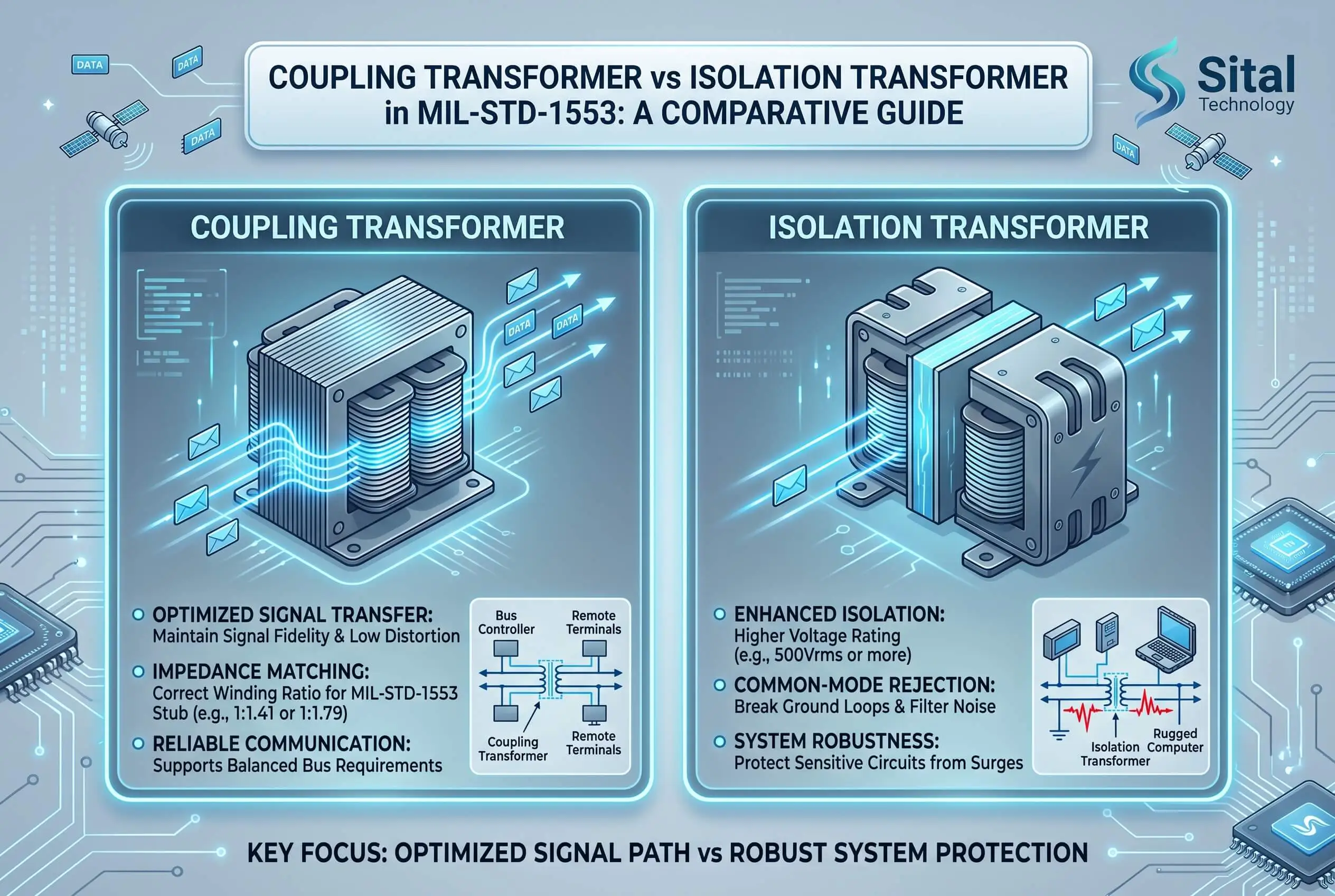
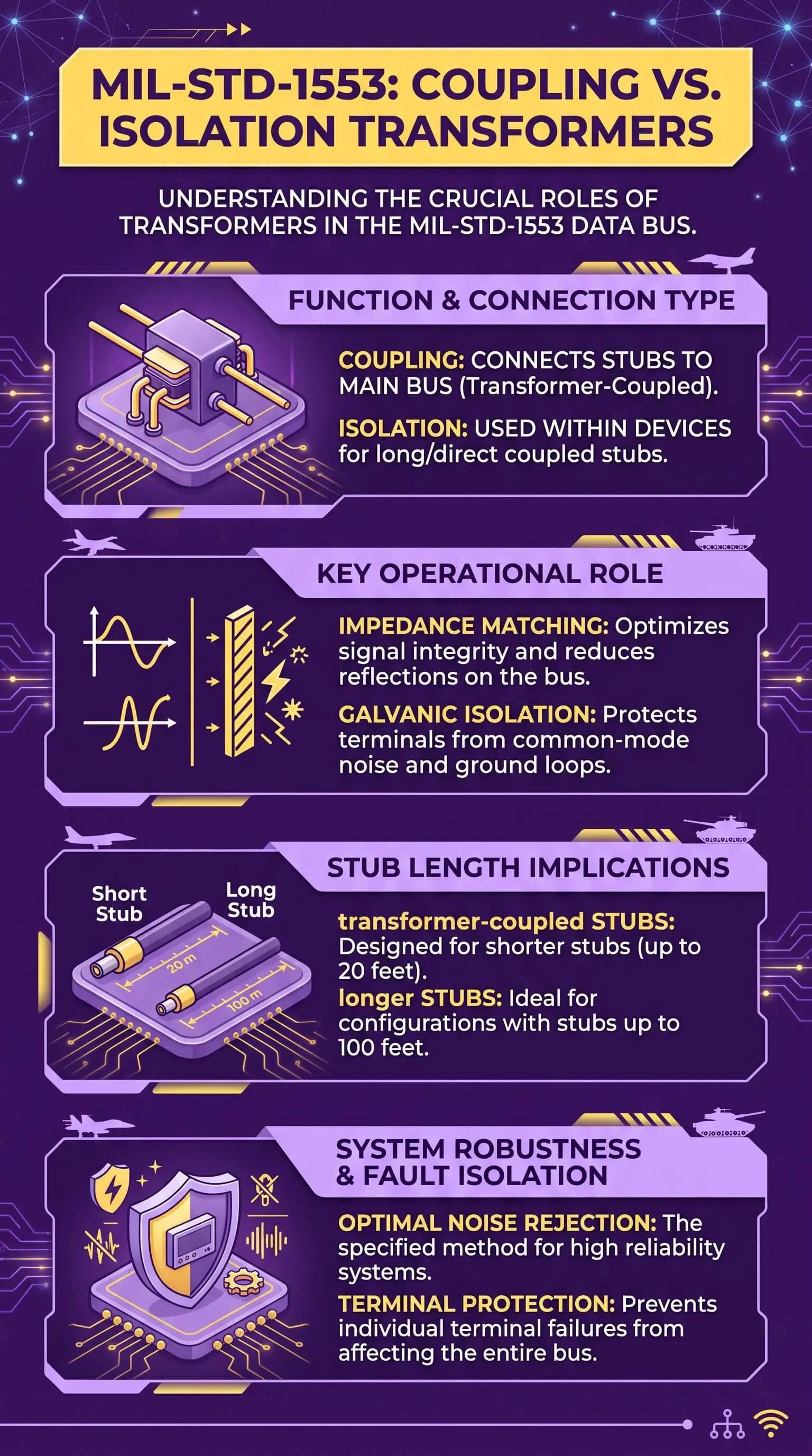
The coupling transformer lives in the bus coupler, a box out on the main bus, separate from the terminal. It shows up only in transformer-coupled stubs. The standard fixes its turns ratio at 1:1.41 and pairs it with two fault-isolation resistors, each at 0.75 times the bus characteristic impedance. That setup matches the stub to the bus, holds signal levels steady, and walls off a faulted stub so a short can't drag down the whole bus. Transformer coupling carries stubs up to about 20 feet.
The isolation transformer lives at the terminal, between the transceiver and the stub. It handles galvanic isolation, common-mode rejection, and impedance matching for that one terminal. Here's what trips people up: the isolation transformer stays at the terminal whether you run transformer coupling or direct coupling. It never leaves.
So the real decision was never coupling transformers against isolation transformers. It's transformer coupling against direct coupling for the stub. Run transformer coupling and the signal passes through a coupling transformer at the bus and an isolation transformer at the terminal. Run direct coupling and you drop the bus-side coupling transformer, wire the stub closer to the bus, and lean on isolation resistors inside the subsystem plus that same terminal isolation transformer.
Which one belongs in your design? The 1553B appendix takes a side. Transformer coupling is the preferred method, and it buys DC isolation, stronger common-mode rejection, roughly double the effective stub impedance, and fault isolation across the full stub and terminal. Direct coupling skips the coupler box and fits very short stubs, but a short between a subsystem's internal isolation resistors and the bus junction can take down that entire bus. Push a direct-coupled stub past about a foot and it starts distorting the main-bus waveform.
Transformer characteristics carry as much weight as the coupling method. Leakage inductance, for one, shapes waveform integrity, so confirm it on the bench before you commit a layout. Here's a practical walk-through on testing leakage inductance in 1553 transformers.
This is where MIL-STD-1553 transceivers and transformers meet. The transceiver drives the Manchester-encoded waveform onto the stub and recovers the messages coming back, and the isolation transformer sits right beside it. Specify the two as a matched pair, or as one integrated transceiver-transformer part, and you cut part count, save board area, and drop a mismatch risk. Several vendors build integrated dual-channel transceiver-transformer parts for exactly that job, Sital among them.
"The mistake I run into most is teams treating the coupling transformer and the isolation transformer as one decision. They aren't. Default to transformer-coupled stubs, keep the isolation transformer matched to its transceiver, and reach for direct coupling only when the stub is short and you can live with weaker fault protection. That order keeps boards off the respin pile."
7 Essential Resources
These references let you check the coupling rules and the transformer specs against primary and vendor sources before you commit a design.
The normative source. The standard defines both coupling methods and the electrical interface. Start here. MIL-STD-1553B on EverySpec
The reasoning behind the rules. The Multiplex Applications Handbook explains why the requirements read the way they do, including the stub-impedance tradeoff that drives the coupling choice. MIL-HDBK-1553A on EverySpec
A designer-friendly overview. DDC's designer notes lay out transformer coupling against direct coupling and the 1:1.41 coupling-transformer ratio in plain terms. MIL-STD-1553 Overview, milstd1553.com
The coupling transformer, section by section. This reference guide breaks out coupling-transformer input impedance, waveform integrity, common-mode rejection, and fault isolation. MIL-STD-1553 Reference Guide (PDF)
A working tutorial. AIM's tutorial covers coupling techniques and terminal interfacing for engineers newer to the bus. AIM MIL-STD-1553 Tutorial (PDF)
Isolation transformer turns ratios in practice. This terminal-design application note spells out the transformer turns ratios used for direct-coupled and transformer-coupled taps. Electrical and Layout Considerations for 1553 Terminal Design, AN/B-27 (PDF)
A transformer-specific primer. This application note separates isolation transformers from bus couplers and shows how each transfers signal and holds isolation. MIL-STD-1553 Transformer Guide, INR Core
3 Statistics
Three numbers show why low-power, well-isolated 1553 hardware keeps earning its place across long programs.
Lifetime cost compounds across decades. The F-35, a heavy user of 1553 and 1760, carries an estimated $1.6 trillion in U.S. sustainment cost as of 2024, and the Department of Defense already flies more than 800 U.S. F-35s with about 1,700 more on the books. A physical-layer choice made once gets multiplied across a fleet that flies for decades. U.S. GAO, F-35 Sustainment, 2025
A deep engineering base specs this hardware. About 71,600 aerospace engineers worked in the United States in 2024, and employment is projected to grow 6 percent through 2034. These are the people integrating 1553 physical layers, and they gain the most from parts that shorten integration time. U.S. Bureau of Labor Statistics, Aerospace Engineers
Defense modernization keeps the demand curve climbing. World military expenditure reached $2,887 billion in 2025, the 11th straight annual rise, with the United States alone at $954 billion. Spending at that level extends fleet life cycles and the retrofit pipeline that both legacy and new 1553 designs feed. SIPRI, Trends in World Military Expenditure, April 2026
These statistics show why EBR 1553 hardware matters across long defense programs: low-power, well-isolated physical-layer choices can reduce integration work, support fleet sustainment, and keep legacy and modernized platforms reliable for decades.
Final Thoughts and Opinion
The "versus" framing is the whole problem. Once you place the coupling transformer on the bus side, in the coupler, and the isolation transformer on the terminal side, where it always lives, the real call comes into focus: which stub coupling method. My position, after enough bench time to hold it firmly, is to default to transformer-coupled stubs and to spec the transceiver and its isolation transformer as one part rather than two you marry later. The teams that pay for it are the ones who dropped the coupler box to save cost, then bought it back in lost fault tolerance and a board respin.
Frequently Asked Questions
Is a coupling transformer the same as an isolation transformer?
No. The coupling transformer sits in the bus coupler on the main bus and ties a stub to the bus. The isolation transformer sits at the terminal and isolates the transceiver from the stub. A transformer-coupled stub uses both.
Does every MIL-STD-1553 terminal need an isolation transformer?
Yes. The isolation transformer stays at the terminal no matter which coupling method you pick. It gives terminal galvanic isolation, common-mode rejection, and impedance matching.
When do you choose transformer coupling over direct coupling?
Make transformer coupling your default, and use it for any stub longer than about a foot. It adds DC isolation, better fault tolerance, and carries stubs up to roughly 20 feet. Direct coupling fits only very short stubs where you can accept the weaker protection, while the right coupling choice can also help improve air quality in the broader sense of keeping signal paths cleaner, more stable, and less prone to electrical noise.
Where does the coupling transformer sit?
Inside the bus coupler box or in-line coupler on the main bus, away from the terminal, at the junction of the main bus and the stub.
Can one part hold both the transceiver and the transformer?
Yes. Integrated transceiver-transformer parts put a transceiver and an isolation transformer in one package, which saves board area and removes a matching step.
CTA
Working out the physical layer for a 1553 or 1760 design? Match the Total-OCTAV MIL-STD-1553 Terminal transceiver and isolation transformer as a pair, run transformer coupling unless the stub is short, and confirm the transformer characteristics on the bench before the first board spin. Request an evaluation or talk to a 1553 applications engineer and pressure-test your approach before you commit.


